1. Site Selection & Geology Assessment
Selecting a building site in mountainous or coastal Norway presents unique geotechnical challenges. The soil profile typically consists of thin organic peat overlying dense moraine clay or barren polished granite (svaberg). Traditional trench footings down to the municipal frost line (which can exceed 1.8 meters in regions like Røros or Hedmark) require heavy excavators that are often impossible to transport across roadless wilderness terrain.
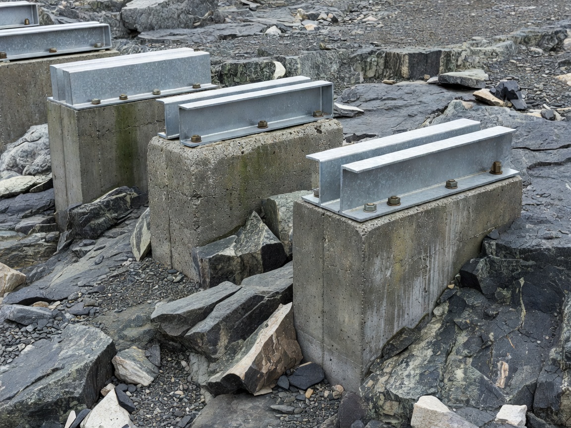
For self-builders, the golden standard is identifying exposed bedrock or solid rock within 300 to 600 mm of the surface. Once cleaned of organic debris and moss with a high-pressure washer or steel brush, the rock becomes the permanent foundation footing.
2. Foundation Methodology: Pillar vs. Ground Screw Comparison
Depending on whether you encounter solid stone or deep gravel moraine, two primary low-impact foundation systems dominate modern Nordic cabin practice:
| Foundation Type | Substrate Applicability | Structural Bearing Cap. | Frost Heave Resistance | Tooling Required |
|---|---|---|---|---|
| Bedrock Concrete Piers | Exposed granite or shallow bedrock (<0.8m) | >80 kN per pier | Absolute (zero movement) | Rotary hammer (SDS Max), 2-part epoxy, Sonotubes |
| Galvanized Ground Screws | Sandy gravel or stone-free clay | 25–45 kN per screw | High (if anchored below frost line) | Hydraulic screw driver or heavy manual lever |
| Leca Expanded Clay Piers | Dry, well-draining non-frost-susceptible soil | 30–40 kN per pier | Moderate (requires gravel base) | Mortar mixer, trowel, gravel compaction tamper |
Drilling and Anchoring into Granite
When anchoring to granite, pneumatic or SDS-Max rotary hammer drills are fitted with 20mm or 22mm carbide masonry bits. Holes are drilled at an angle of 90 degrees to the rock plane to a depth of at least 150 to 200 mm. After drilling, the boreholes are blown out with compressed air and wire brushes to remove all stone dust.
Hot-dip galvanized threaded rods (Class 8.8 M16 or M20) or ribbed rebar pins are set with structural vinylester or pure epoxy resin. The chemical bond ensures tensile pull-out values exceeding 45 kN per anchor point, effortlessly resisting wind overturning forces during Atlantic gale storms.
3. Timber Framing & C24 Joist Calculations
Nordic timber framing utilizes strength-graded European spruce (Picea abies), denoted under EN 338 as grade C24. C24 offers a characteristic bending strength of 24 N/mm² and a mean modulus of elasticity parallel to grain of 11,000 N/mm².
For a typical 6.0m by 6.0m cabin layout supported on three longitudinal glulam or triple 48x198mm bearer beams, the floor joists span 3.0 meters between beams.
Nordic Standard: C24 Joist Span Schedule for 4.0 kN/m² Snow Region
- Joist Size 48x148mm: Maximum span 2.30 m at 600 mm on-center (c/c).
- Joist Size 48x198mm: Maximum span 3.10 m at 600 mm c/c (Ideal standard).
- Joist Size 48x223mm: Maximum span 3.75 m at 600 mm c/c (Allows clear spans with no centre pier line).
4. Subfloor Decking and Under-Floor Thermal Isolation
Cold subfloors are the primary cause of comfort complaints in DIY winter cabins. Because the cabin sits on open pillars, freezing Arctic air circulates under the floorboards at temperatures down to -25°C. The subfloor stack must be engineered from bottom to top:
- Asphalt-impregnated wind-barrier board (12mm): Fastened directly beneath the joists to stop wind wash from pulling warmth out of the insulation.
- 200mm Mineral Wool (Rockwool or glass wool): Friction-fit between the C24 joists with zero gaps.
- Vapour barrier or vapour retarder: Installed on the warm side of the insulation, taped with moisture-resistant acrylic tape.
- Tongue-and-groove structural subfloor (22mm spruce or moisture-resistant P5 chipboard): Glued and screw-fastened to the joists to prevent seasonal floor squeaks.
5. Snow Load Mechanics & Foundation Reaction Points
In southern Norway, ground snow loads range from 2.5 kN/m² along coastal Oslofjord up to 6.5 kN/m² in mountainous regions like Hemsedal or Sirdal. For a 40 m² roof area with a ground load of 5.0 kN/m², the building must safely carry up to 20 metric tonnes of snow weight alone, not including deadweight and occupancy.
Distributing this force down through 12 to 16 concrete piers translates to approximately 1.5 to 2.0 tonnes of downward compressive force per pier. The bedrock easily withstands this compressive load, provided the timber connection bracket uses heavy-gauge 6mm steel plates with through-bolts rather than lightweight screws.